Physical Computing - Buzzers, Serial Communication, and AD/DA Converters

Adam Boucek
|October 6th 2023
In this lab, we will continue with another set of projects you can create with ESP32-WROVER. Instructions are given by Andrew J. Park, Ph.D..
We will use Freenove Ultimate Starter Kit for ESP32-WROVER which you can buy on Amazon. How to set up the kit and start uploading code you can find on Freenove.
If these projects seem too challenging you can do the Freenove tutorials.
Project 1 - Buzzer, LED, and two push buttons
Date: 10/02/23
Instructions:
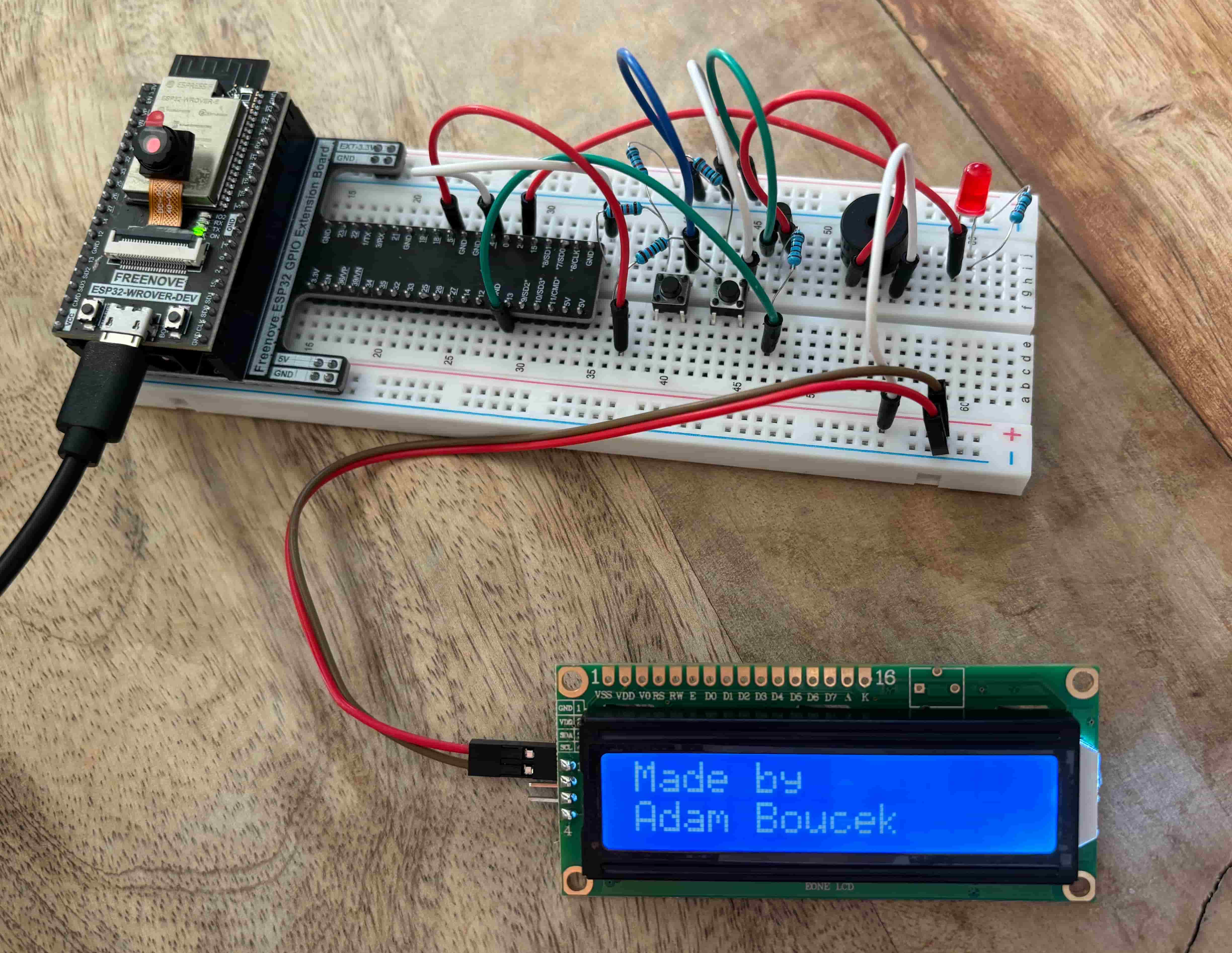
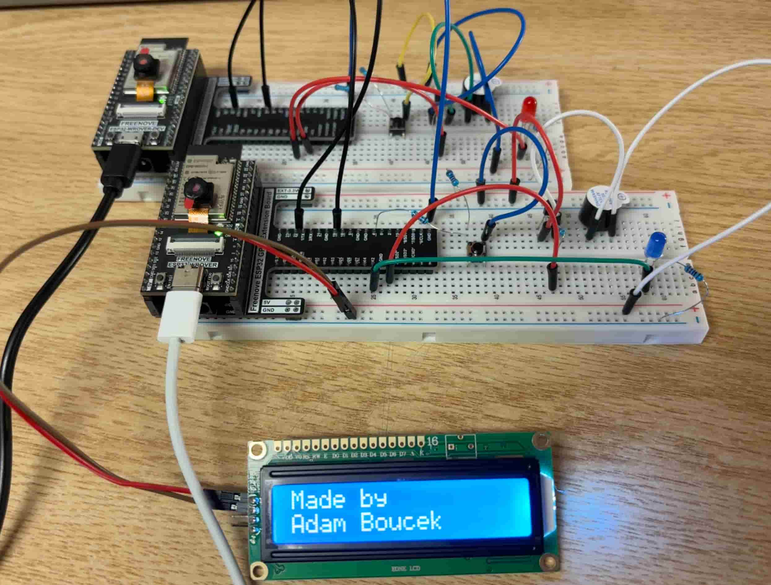
Design and construct a circuit with a buzzer, an LED, and two push buttons (and other necessary electronic components). The LED light blinks when one push button is pressed, and the song “Row, Row, Row Your Boat” is played. The LED light stays on when the other button is pressed, and the song “Mary Had a Little Lamb” is played. Capture your settings and working circuit in photos and videos (the videos should include the melodies).
Parts:
- ESP32-WROVER x1
- GPIO Extension Board x1 (optional)
- Breadboard x1
- Jumper M/M x6
- Passive Buzzer 1x
- Push Buttons x2
- NPN transistor x1
- LED Bar 1x
- Resistor 1kΩ x6
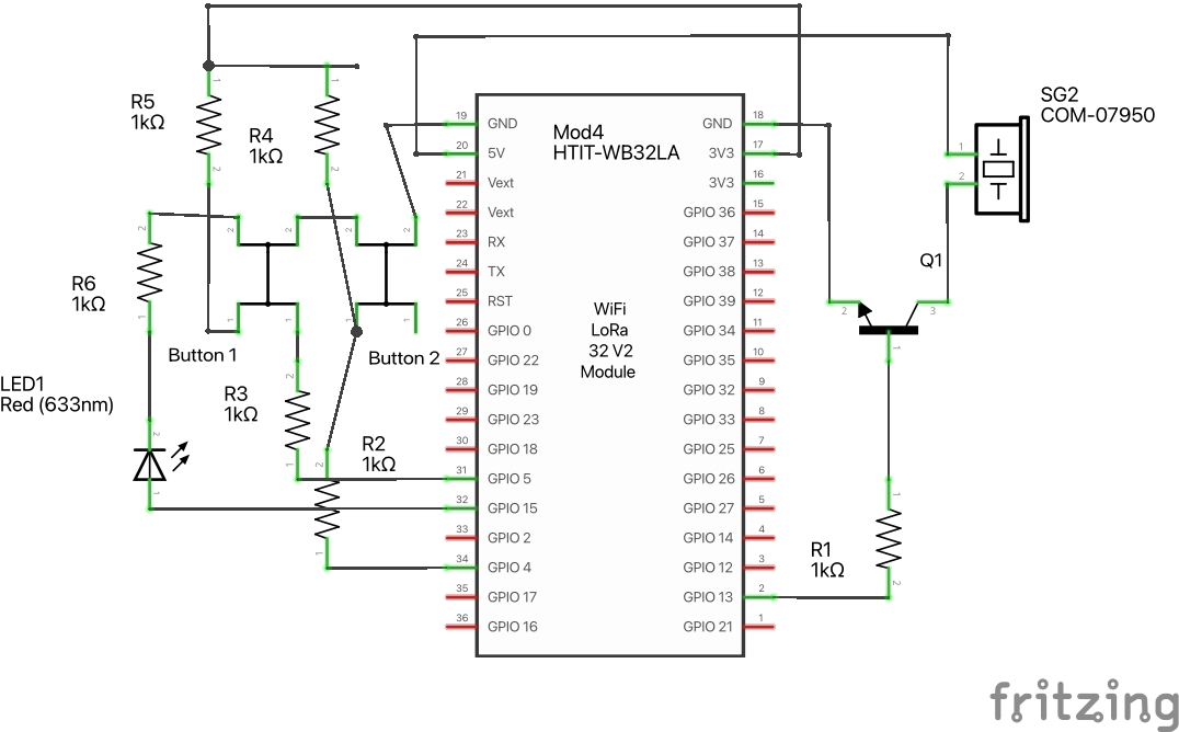
LED Bar schema:
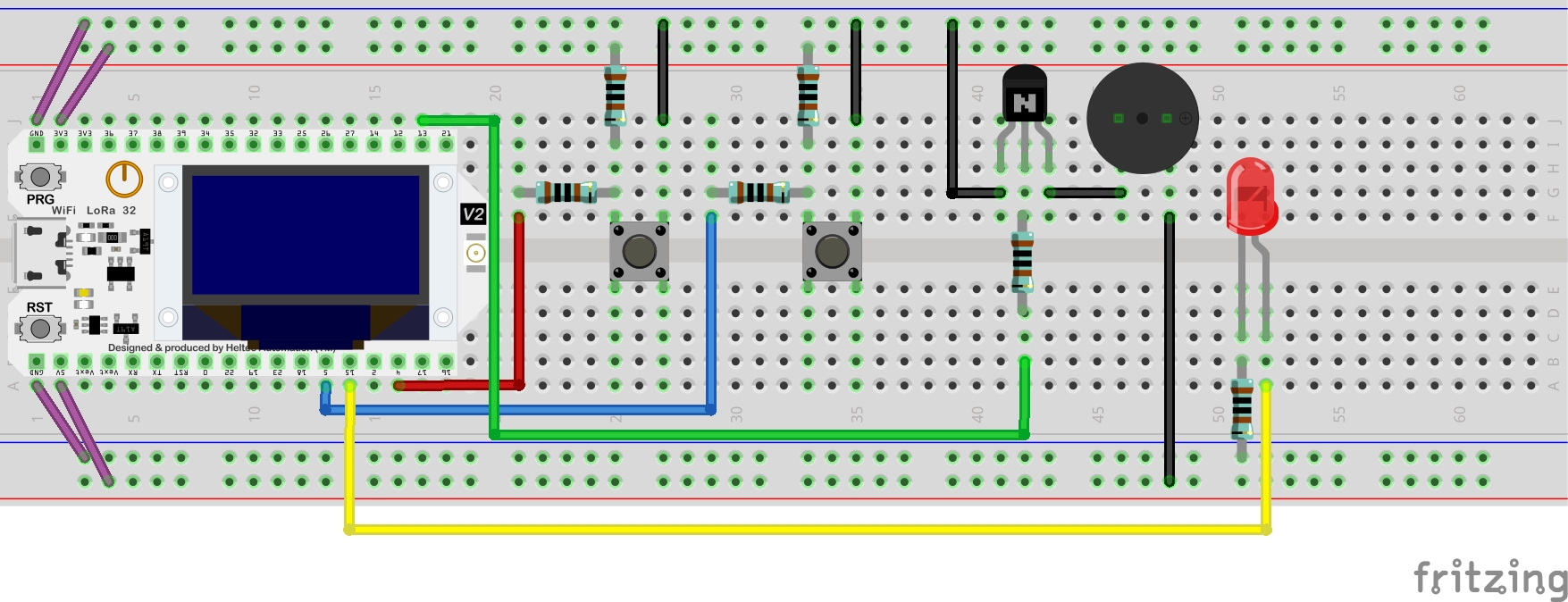
LED Bar Breadboard View:
Source Code:
project-1.py
from machine import Pin, PWM
import math
import time

# Defining note frequency
NOTE_C4 = 262
NOTE_D4 = 294
NOTE_E4 = 330
NOTE_F4 = 349
NOTE_G4 = 392
NOTE_A4 = 440
NOTE_B4 = 494
NOTE_C5 = 523
NOTE_D5 = 587
NOTE_E5 = 659
NOTE_F5 = 698
NOTE_G5 = 784
NOTE_A5 = 880
NOTE_B5 = 988

# Notes for "Row, Row, Row Your Boat"
row_notes = [
    NOTE_C4, NOTE_C4, NOTE_C4, NOTE_D4, NOTE_E4,
    NOTE_E4, NOTE_D4, NOTE_E4, NOTE_F4, NOTE_G4,
    NOTE_C5, NOTE_C5, NOTE_C5, NOTE_G4, NOTE_G4, NOTE_G4, NOTE_E4, NOTE_E4, NOTE_E4, NOTE_C4, NOTE_C4, NOTE_C4,
    NOTE_G4, NOTE_F4, NOTE_E4, NOTE_D4, NOTE_C4
]

# Notes for "Mary Had a Little Lamb"
marry_notes = [
    NOTE_E4, NOTE_D4, NOTE_C4, NOTE_D4, NOTE_E4, NOTE_E4, NOTE_E4,
    NOTE_D4, NOTE_D4, NOTE_D4, NOTE_E4, NOTE_E4, NOTE_E4,
    NOTE_E4, NOTE_D4, NOTE_C4, NOTE_D4, NOTE_E4, NOTE_E4, NOTE_E4,
    NOTE_E4, NOTE_D4, NOTE_D4, NOTE_E4, NOTE_D4, NOTE_C4
]

button = Pin(4, Pin.IN, Pin.PULL_UP)
button2 = Pin(5, Pin.IN, Pin.PULL_UP)
passiveBuzzer = PWM(Pin(13), 2000)
ledRed = Pin(2, Pin.OUT)

def rowRow():
    for i in range(len(row_notes)):
        passiveBuzzer.freq(row_notes[i])
        ledRed.value(1)
        time.sleep_ms(100)
        ledRed.value(0)
        time.sleep_ms(100)

def mary():
    for i in range(len(marry_notes)):
        passiveBuzzer.freq(marry_notes[i])
        ledRed.value(1)
        time.sleep_ms(200)
    ledRed.value(0)
    time.sleep_ms(200)

try:

    while True:
        if not button.value():
            passiveBuzzer.init()
            rowRow()

        if not button2.value():
            passiveBuzzer.init()
            mary()
            ledRed.value(0)

        passiveBuzzer.deinit()
except:
    passiveBuzzer.deinit()
Youtube video ↓ (click on it)

Project 2 - Serial Communication between two ESP32
Date: 10/05/23
Instructions:
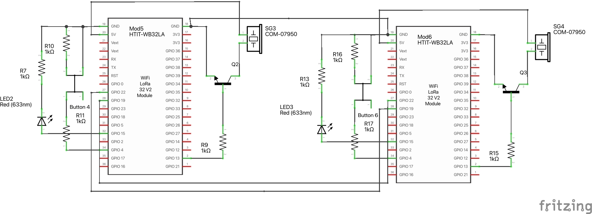
This project needs two ESP32s. You need to work with a partner (classmate). Each ESP32 needs a push button, LEDs, and a buzzer, (and other necessary electronic components). Design and construct a circuit for each ESP32 so that the two ESP32s do serial communication using UARTs. When a pushbutton is pressed from one ESP32 (A), the other ESP32 (B) responds by blinking LEDs and playing some sound. When a pushbutton is pressed from the other ESP32 (B), ESP32 (A) responds by blinking LEDs (a different pattern from the LEDS on ESP32 (B)) and playing some other sound. Capture your settings and working circuit in photos and videos (the videos should include the sounds).
Parts:
- ESP32-WROVER x2
- GPIO Extension Board x2 (optional)
- Breadboard x2
- Jumper M/M x15
- Active Buzzer 2x
- Push Buttons 2x
- NPN transistor x2
- LED Bar 2x
- Resistor 1kΩ x6
- Resistor 200Ω x2
Serial Communication between two ESP32 schema:
Serial Communication between two ESP32 Breadboard View:
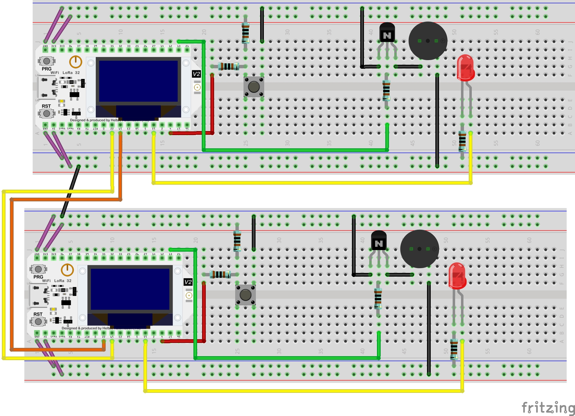
Note: Use 22 and 19 for RX and TX if you use two ESP32
Source Code:
First ESP32
from machine import Pin, UART
import time

myUart = UART(1, baudrate=9600, bits=8, parity=0, rx=19, tx=22, timeout=10)

button=Pin(4,Pin.IN,Pin.PULL_UP)
activeBuzzer=Pin(13,Pin.OUT)
ledRed = Pin(12, Pin.OUT)

activeBuzzer.value(0)


while True:
    receivedData = myUart.read()
    if not receivedData:
        if not button.value():
            myUart.write(str("Go"))

    else:
        activeBuzzer.value(1)
        ledRed.value(1)
        time.sleep_ms(1000)
    activeBuzzer.value(0)
    ledRed.value(0)
Second ESP32
from machine import Pin, UART
import time

myUart = UART(1, baudrate=9600, bits=8, parity=0, rx=19, tx=22, timeout=10)

button=Pin(4,Pin.IN,Pin.PULL_UP)
activeBuzzer=Pin(13,Pin.OUT)
ledRed = Pin(12, Pin.OUT)

activeBuzzer.value(0)


while True:
    receivedData = myUart.read()
    if not receivedData:
        if not button.value():
            myUart.write(str("Go"))

    else:
        activeBuzzer.value(1)
        ledRed.value(1)
        time.sleep_ms(1000)
    activeBuzzer.value(0)
    ledRed.value(0)
Result:

Blog Link: https://www.boucek.dev/blog/physical-computing-Buzzers-Serial-Communication